
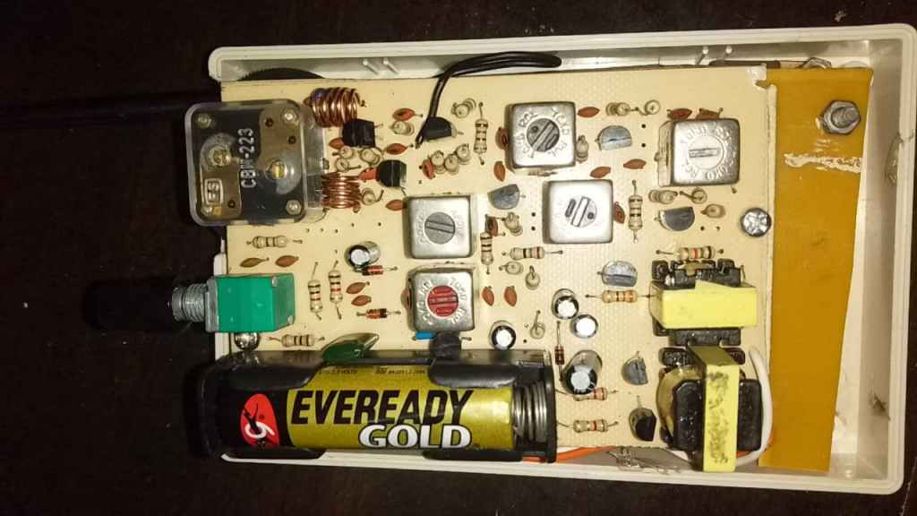
All transistor MW pocket radio is common can be found and most fm radio are build with IC. I found a MW/SW 2 band NOS pearl rive china brand germanium transistor radio from local old electronics trading shop. They operate at single D cell . The volume is impress me, Most of pocket radio they are operate at 3V or 2 AA cell .. I never see 1.5V radio before, i make some research that in old day battery are expansive in china in order to make the radio last longer they design it into single cell . Below video show the radio receive a noise pick up from main electrics, in malaysia we dont have MW station and SW station cant receive inside my apartment i just show how loud it can be with single D cell.
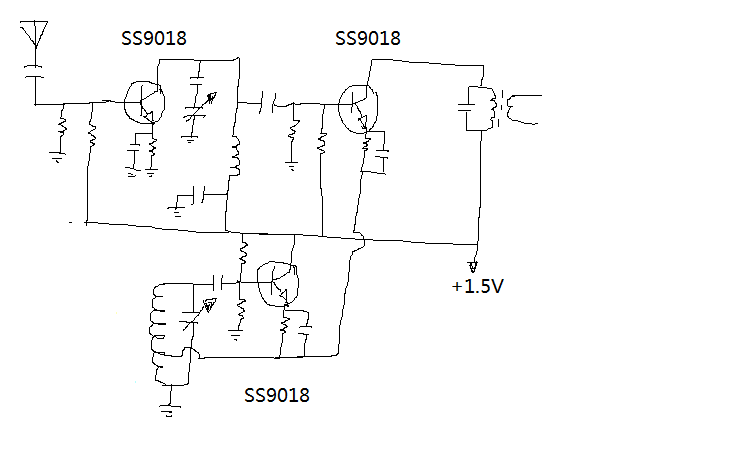
Below is my first scratch of RF amp , Mixer and Local oscillator, I have alot SS9018 and SS9018 having 1.1Ghz of ft i can use it for RF , mixer , Local oscillator and IF amplifier. I test the circuit below in Lt spice and found there is some mistake for connect mixer RE to Oscillator coil Center tap. so i modified it into through a capacitor coupling into Mixer emitter.
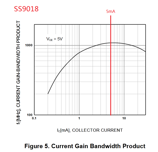
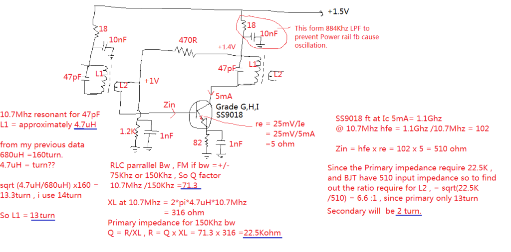
Below is my scartch of IF stage amplifier schematic. The IF can data from my previous 2 band radio reserve engineering 180turn giving about 680uH inductance when the slug is adjust in middle. So i can use that data to calculate 4.7uH require how many turn i’m using 13 turn . In Order to maximize of SS9018 of gain the Ic require to operate at about 5mA. During SS9018 operate at ft (transition frequency) , the hfe is unity which is 1 , so the hfe increase by 10 when frequency go down 10 times of ft such as 110Mhz hfe is 10 and so on.. so in most of my circuit i’m using 470R and 1.2K potential bias configuration to set the Vbase voltage at about 1V. since the Vbe about 0.65V so the voltage drop arcoss 82 ohm about 4.26mA which slightly lower then 5mA so should be ok.
For Audio amplifier section , I plan to use ferrite core as Input output transformer. The reason is ferrite core is easy to obtain now a days from cheap USB charger…etc There a page i experiment for clone ST-32 Output transformer by using ferrite core.

After having the all concept of the schematic so i try to design the layout as below. I try to make it as small as possible.. there is RF and Mixer and LO part is incomplete.
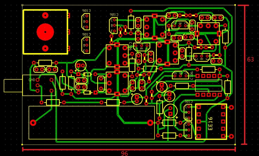
Signal path from antenna to speaker.

After complete the layout design i using toner transfer method to fab the PCB.. I find the scarp IF-CAN for rewind and some scarp EE13 as input transformer and EE16 as output transformer. For PCB layout in PDF click Here.

After complete Toner transfer by using Hot iron.
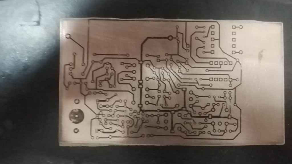
After etching the copper and the trace look good , i need to use sand paper to remove the carbon on top then apply flux and tinned a layer on trace to prevent oxidation.

The EE13 and EE16 ferrite core is put in hot boiling water for cook 5-10min to remove the varnish.

Need to careful remove the core to prevent break.

Rewind the core for EE13 input L4/L5 using 0.15mm (SWG38) wind 100turn , L6 wind 200turn . (later i improve the bass response by change the wire to 0.1mm (SWG41) wind L4/L5 for 250turn and L6 wind 500turn.)
For output transformer using EE16 L1/L2 120turn using 0.15mm(SWG38) wire and L3 120turn with 0.25mm CCA wire (i dont have copper wire , so copper wire work better then CCA) . Later i improve the output power by remove L3 , so only L1 and L2 with 0.25mm CCA wire and 2 end of the transformer connect to 8 ohm speaker.

Completed audio amplifier section and found that the output volume is weak and lack of bass so i improve the Input transformer and output transformer winding by change the wire to 0.1mm (SWG41) wind L4/L5 for 250turn and L6 wind 500turn and remove L3 , so only L1 and L2 with 0.25mm CCA wire and 2 end of the transformer connect to 8 ohm speaker. Below photo show transformer after soap in varnish.


Below Improve bass response and output volume.

I remove all wire from scarp IF can , most of them are 455Khz AM radio IF can and there is 1 is MW oscilator coil.
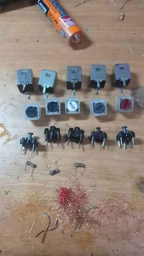
Completed one of IF can.

Inductance measure 4.7uH

Ratio Discriminator winding information.

below show completed solder all IF can into PCB and IF amp and discriminator is ready to test.
I’m simply using NanoVNA as sweep from 10Mhz to 11Mhz and the discriminator connect to Oscilloscope it show a sawtooth waveform.

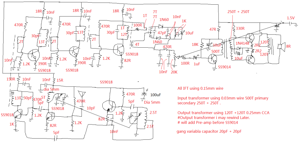
The first completed schematic , the IF can capacitor i have to chance to 30pF instead of 47pF is due to the parasitic capacitor and cause the resonant below 10.7Mhz so i change to 30pF now able to tune all IF can into 10.7Mhz. I also reduce the stage 1 and 2 of IF amplifier gain by increase emitter resistor from 82 ohm to 390 due to it oscillate within the stage. and i keep the last stage for 82 due to the last stage require some power to drive the diode. This is not final schematic it contain some error.
The first power up i can heard some station the volume is very weak also the tone is very sharp (later i found due to my discriminator out of tune) . I using PC speaker to make additional audio gain.
Since the volume is so weak i connect the output to earphone place earphone close to phone microphone to make a video record.
After re-tune ratio discriminator CAN it sound better.
After added Pre-amp now the volume sound alot better.
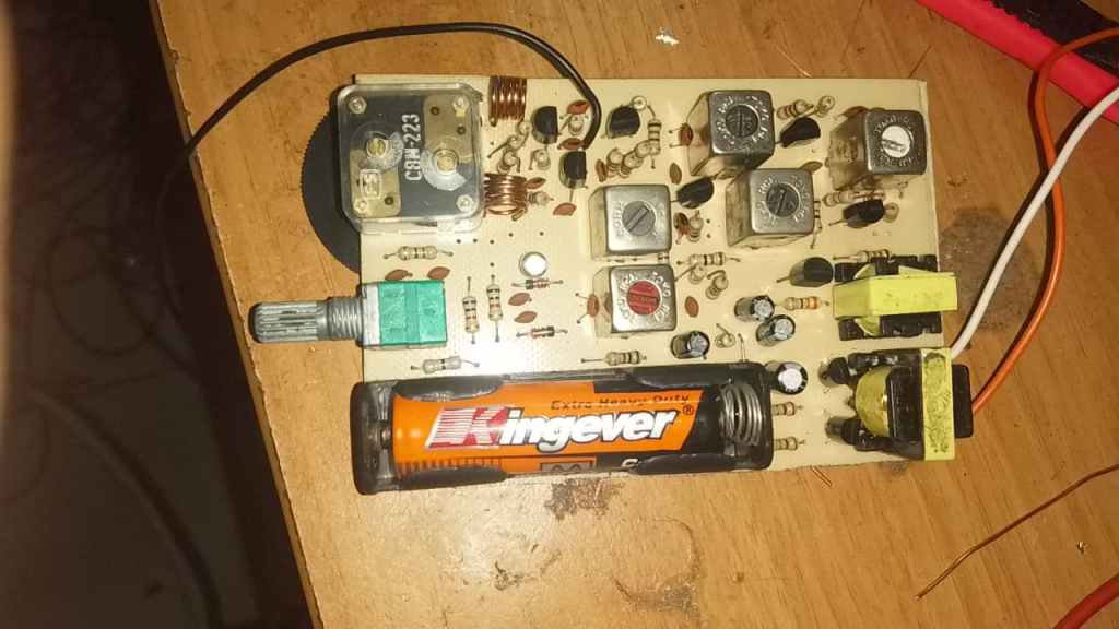
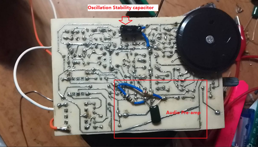
below show the Modification by add SS9014 as audio pre-amp . the top 100uF for Oscillator stability. (later i change to 10V 2200uF)

The final schematic except there is a mod for 16V 100uF at oscillator power rail i change to 10V 2200uF for better stability. Because the power supply only 1.5V there is not headroom for voltage regulator .

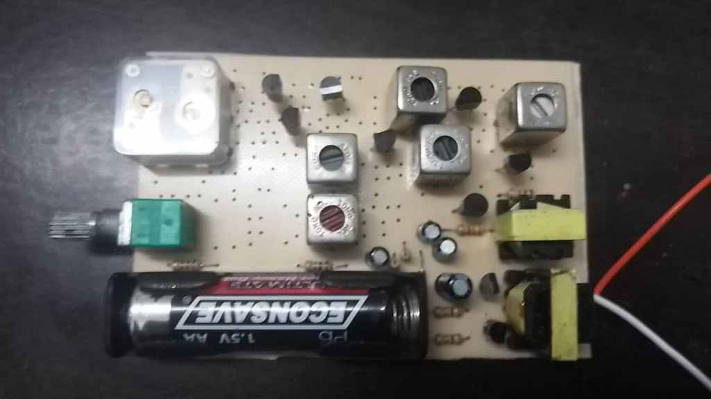
I build everything into plastic case unfortunately the back cover no enough deep so i cant close up. i will leave it like this. below photo show the oscillation stability capacitor is 16V 100uF and later i change to 10V 2200uF

I bring out to test at outside my house car park. it work well , the volume sound like pocket size MW radio.
